OneDDL
CMTeamPK Member
Offline
Free Download Autodesk AutoCAD Plant 3D 2025 with Offline Help | 3.6 Gb
Autodeskhas releasedAutoCAD Plant 3D 2025 Toolsetis an extension of AutoCAD, a computer-aided design (CAD) application intended for engineers, architects and construction experts to develop 2D and 3D drawings of products and workpieces with precision.
Owner:Autodesk
Product Name:AutoCAD Plant 3D Toolset
Version:2025 with Offline Help *
Supported Architectures:x64
Website Home Page :
Languages Supported:english
System Requirements:Windows **
Size:3.6 Gb
AutoCAD_Plant_3D_2025_English_Win_64bit_db_001_002.exe
AutoCAD_Plant_3D_2024_English_Win_64bit_db_002_002.sfx.7z
Object_Enabler_for_AutoCAD_Plant_3D_2025.exe
Offline_Help_for_AutoCAD_Plant_3D_2025_English.exe
What's New in AutoCAD Plant 3D 2025 Toolset
Enhanced P&ID Modeler (What's New in 2025)
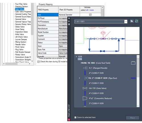
The P&ID line list has undergone a complete redesign and improvement, resulting in the creation of an enhanced P&ID modeler. This new modeler provides a more comprehensive view of the P&ID drawing, displaying all line segments and their associated components such as inline components, nozzles, start/end equipment models, branches, and off-page connectors.
With the P&ID Line List window, you can now easily select any available P&ID object and place its corresponding Plant 3D counterpart in the 3D model. This ensures that the property values of the P&ID object are accurately copied to the 3D model.
Note: For accurate placement of Plant 3D objects in the model, it is highly recommended to map a P&ID object to its corresponding Plant 3D object before placement. If unmapped items are placed, the Custom Parts dialog box is displayed.
P&ID line segments are always mapped to Plant 3D pipes.
Close
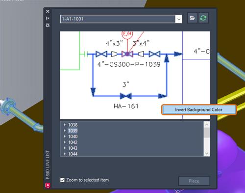
You can customize the background color of the P&ID preview. Right-click the P&ID preview and choose Invert Background Color.
Close
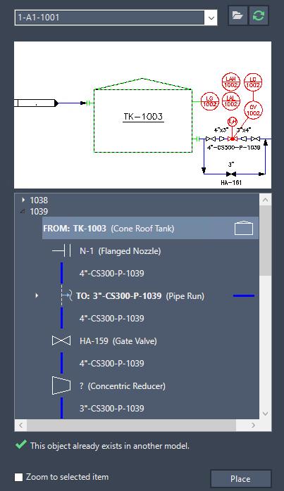
To place these items in the 3D model, choose the desired start or end equipment and nozzle, and map them to their corresponding Plant 3D counterparts.
Once a P&ID equipment is placed in the 3D model, click on a nozzle in the tree view to place it as well. If the nozzle has already been placed in the 3D model, the Edit Nozzle dialog box is displayed. If the nozzle has not been placed yet, the Add Nozzle is displayed instead.
Note: When a specific nozzle tag exists in the Plant 3D equipment template, the property values of all nozzles are copied to the Plant 3D nozzles.
Close
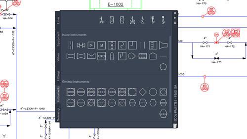
P&ID ISA Symbology Updates (What's New in 2025)
The P&ID ISA symbols have been updated to match the latest ISA standard. Here are the detailed changes that have been implemented:
- All existing ISA instrumentation symbols have been modified to conform to the ANSI/ISA-5.1-2022 standard. The dimensions of these symbols have been adjusted accordingly.
Close
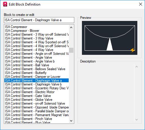
- Missing instrumentation symbols specified in the ANSI/ISA-5.1-2022 have been created and included. These newly added symbol blocks are prefixed with "ISA" and can be found in projSymbolStyle.dwg.
Close
- The existing graphic symbols for process displays have been updated to align with the ISA-5.5-1985 standard.
Close
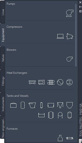
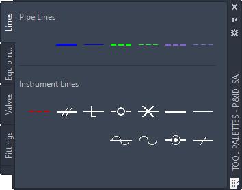
- The images of the existing symbols in the substitution and Tool palettes have been updated to reflect the changes made to the ISA symbology.
- The symbol settings in the Project Setup have been updated to accommodate the changes made to the existing symbols.
- The existing linetypes in pid_custom.lin have been modified to align with the ANSI/ISA-5.1-2022 standard.
Close
- Additional linetypes defined in the ANSI/ISA-5.1-2022 have been created and stored in pid_custom.lin and pidcustom.shx files. To load the updated linetypes, use the LINETYPE command.
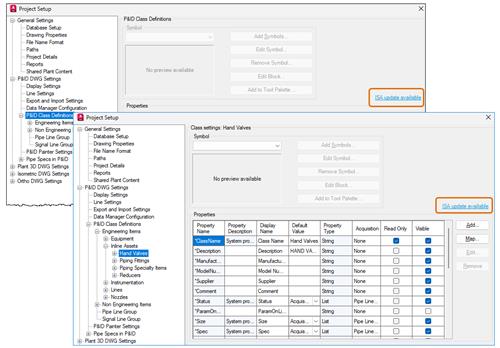
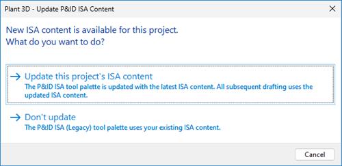
Additionally, a migration check has been implemented to validate legacy ISA projects when they are opened. When you open an ISA project that's created in an earlier version, the "ISA update available" link is displayed on the P&ID Class Definitions node and on each of its child pages. Click the link to open the Plant 3D - Update P&ID ISA Content dialog box.
Close
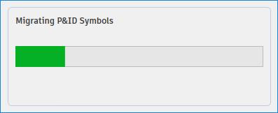
If you choose to update the ISA content, a task dialog is displayed to monitor the progress of migrating P&ID symbols. This allows you to track the status of the symbol migration process.
Close
Once the migration is complete, run the SYNCHSTYLES command to update the existing symbols in the current drawing to the latest version.
Close
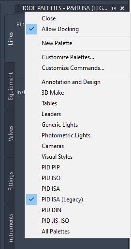
You can still work with legacy ISA symbols even if you choose not to update the ISA content. Select the P&ID ISA (Legacy) option from the Tool palette to continue using the legacy ISA symbols in your project.
Close
Note: If you copy a drawing using legacy ISA symbols into a new project, run command SYNCHSTYLES to update the existing symbols to the latest version in the drawing.
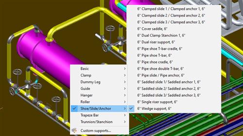
Pipe Support Substitution (What's New in 2025)
After placing a pipe support in the 3D model, you can easily switch to a different pipe support using the substitution grip. You can substitute the pipe support with another available pipe support from the project's pipe support spec or with a custom pipe support.
Close
Ortho Enhancements (What's New in 2025)
Inheriting Ortho Layers from 3D Models
Ortho layers can now inherit the same 3D model layer scheme, resulting in improved management of ortho objects. When you choose to use 3D model layers in Ortho Generation Settings from Project Setup, ortho objects can now adopt the same layering scheme as the 3D model. If your 3D models are created by converting AutoCAD blocks that contain multiple layers, the resulting ortho views will represent all the layers, allowing you to differentiate individual parts of the object. You can change individual layers in ortho drawings to control different parts on the objects. Additionally, if your 3D models are imported from other products such as Advance Steel, AutoCAD Architecture, AutoCAD MEP, and others, the embedded layers in these models are reflected in the ortho drawings. You can still change individual layers in ortho drawings to control different parts on the objects, regardless of the source of 3D models.
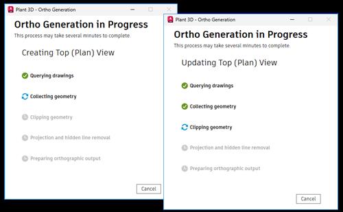
Ortho Generation Interface
This release introduces a modern and user-friendly dialog interface to enhance the monitoring of ortho generation progress. The Ortho Generation dialog box has been redesigned with a modern style, providing a more visually appealing and intuitive interface.
Close
You also have the flexibility to drag the Ortho Generation dialog box to any location as needed. To optimize your workspace, you can also minimize the dialog box to the taskbar.
Note: During the ortho generation process, it is recommended not to perform any operations in the application. If you need to abort the ortho generation process, you can cancel it directly from the dialog box.
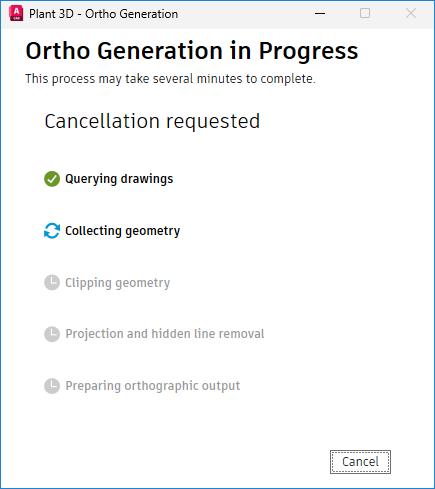
Close
Updating Ortho Views
Previously, you could only update views in an ortho drawing from the right-click menu in the Project Setup. Now, we have introduced a new option to update views using the command line as well.
To update all views together in an ortho drawing, use the new All option in the PLANTORTHOUPDATE command.
A new system variable, PLANTORTHOSILENTUPDATE, is introduced to allow automatic updates for all views, bypassing any warning dialogs that may display. PLANTORTHOSILENTUPDATE is designed to ignore the following cases:
- Views that are already up to date.
- Views that consist of missing 3D models.
- Original 3D models that consist of proxy objects.
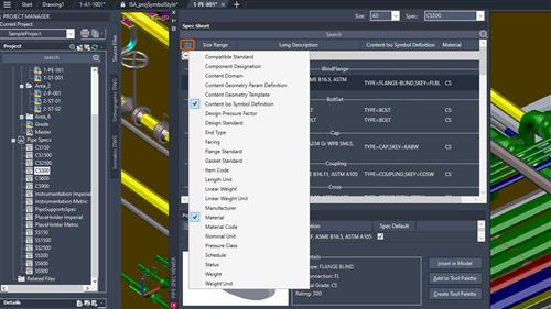
Pipe Spec Viewer Column Customization (What's New in 2025)
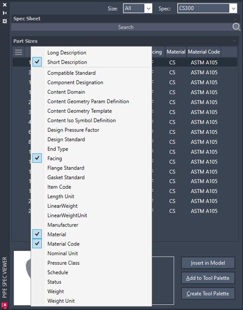
The Pipe Spec Viewer now allows you to customize columns and search non-display properties. A column customization functionality has been added at the top left of both Spec Sheet and Part Sizes. Click the button to display the property list where you can choose specific properties to display in the columns. You can also manually adjust the location of each column by dragging them.
Close
If you have already added custom properties from Spec Editor, they are displayed in the property list flyout. Custom part family properties are displayed in the Spec Sheet property list, while the custom part size properties are displayed in Part Sizes.
Note: The previous three size columns have been consolidated into a single column (Size Range). You can choose whether to display the long description or the short description for part sizes.
Close
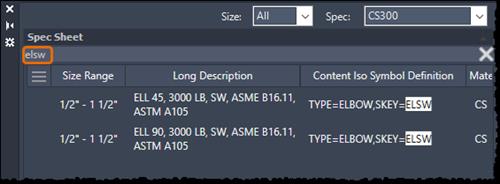
You can search for properties even if they are not currently displayed in the columns. When you hover over the search results, a tooltip is displayed to indicate which property includes the search text. For example, if you type "elsw" in the search box, all elbows with Skey=ELSW are displayed in the search results.
Close
Spec Editor Column Customization (What's New in 2025)
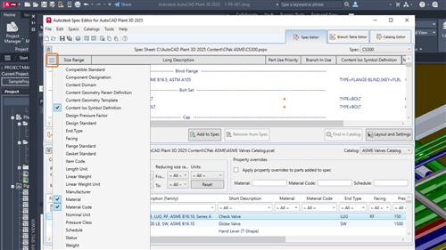
You can now customize the columns in the Spec Editor according to your preferences. To customize the columns, click the column customization button at the top left of the Spec Editor. Clicking the button displays the property list where you can choose specific properties to display in the columns. You can also manually adjust the location of each column by dragging them.
Close
If you have already added custom properties, they are displayed in the property list flyout. Custom part family properties are displayed in the Spec Sheet flyout property list, while the custom part size properties are displayed in Part Sizes. However, only the custom part family properties are displayed in the list.
Note: The previous three size columns have been consolidated into a single column (Size Range).
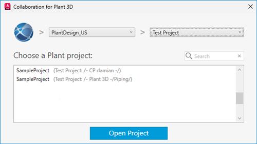
Collaboration Projects in Autodesk Docs Subfolders (What's New in 2025)
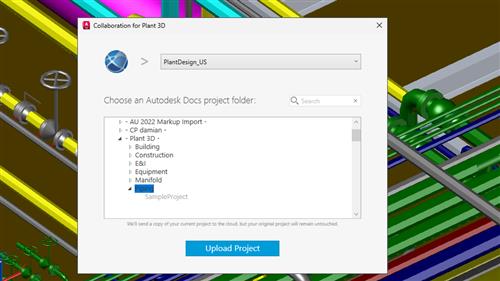
You can now collaborate on projects within subfolders in Autodesk Docs. This functionality is particularly useful when sharing a Plant project to the cloud.
Close
After you select the Autodesk Docs account from the drop-down list, a list of all the Docs project folders including their respective subfolders is displayed. You have the option to choose either the parent folder or expand it to select a specific subfolder, which serves as the project path for collaboration.
You can also use the search box to quickly find the desired project folder. When you enter a search term, any matching results are displayed in bold.
Note: Only the expanded folders are searchable as this helps improve performance and efficiency.
When opening a collaboration project, you can select a Plant project from the Autodesk Docs account, provided you have necessary access permissions.
If projects share the same name, the project path are displayed alongside the name, offering you better options and clarity.
Close
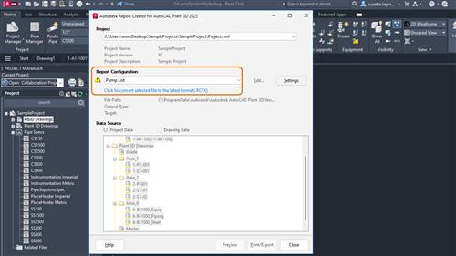
Report Creator Configuration Files Format (What's New in 2025)
Starting from AutoCAD Plant 3D 2025, the report configuration files are updated to the new RCFX format.
Close
If you are using the 2024 version or earlier, the older rcf format is not compatible with the current version. To ensure compatibility with the Report Creator, you need to migrate any existing rcf files to the new rcfx format.
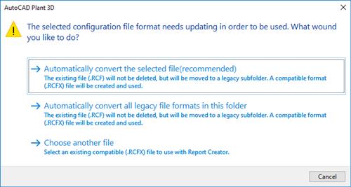
When you select a legacy report configuration file, a warning message is displayed. Follow the necessary steps to proceed.
Close
For handling legacy report configuration files, you have three options to choose from:
- Convert the selected legacy file to the updated format file automatically. A legacy subfolder is created to store the original legacy file.
- Convert all the legacy files to the updated format file automatically. Similar to the previous option, a legacy subfolder is created to store the original legacy files.
- Exit the dialog box and go back to Report Configuration dialog box to choose an updated format file.
Note: The updated RCFX files are not compatible with AutoCAD Plant 3D 2024 version or any earlier versions.
Additional enhancements
- AutoCAD Plant 3D 2025 now supports customization of lap end types for 3D piping.
- Renaming or moving folders from the Project Manager now automatically updates the changes in the Windows File Explorer. This ensures that any folder manipulations made within a collaboration project are reflected in the Autodesk Docs Viewer.
- Weld symbols can now be displayed in both the Autodesk Docs Viewer and Navisworks.
Autodesk AutoCADis computer-aided design software that allows you to efficiently create and document 2D and 3D designs. Industry-specific Autodesk tools, such as architecture, plant 3D, map 3D, MEP, electrical, mechanical and grid design, make Autodesk AutoCAD the number one software for architects, engineers and construction professionals.
Autodesk AutoCAD 2025enhances your 2D and 3D design experience with features that unlock insights and automations with the help of Autodesk AI, tailors to discipline-specific workflows, and stay connected with one experience on desktop, web, and mobile-to capture, share, and review ideas on the go.
TheAutoCAD Plant 3D toolsethelp plant designers create and edit Piping & Instrumentation Diagrams (P&IDs) and to generate and modify process plant models, which they use to produce piping isometrics and piping orthographic drawings.
Introduction to the AutoCAD Plant 3D Toolset
With the introduction of the industry-specific toolsets included in the AutoCAD subscription, identifying the right toolset for your business can be overwhelming. Many companies work with multiple disciplines and need to work with a variety of AutoCAD software applications, and now thanks to One AutoCAD, they can. In this series we will focus on each toolset so that you can easily choose which one is best for your application. This webinar is intended for AutoCAD Users new to the toolsets.
Autodeskhelps people imagine, design and create a better world. Everyone-from design professionals, engineers and architects to digital artists, students and hobbyists-uses Autodesk software to unlock their creativity and solve important challenges.

Links are Interchangeable - No Password - Single Extraction


